Undo and Redo allow users to
quickly and easily reverse drawing operations in order to correct mistakes or
to try alternatives.
Visual CADD™ differs from many other applications in the
way undo and redo are internally implemented, although
the results for the end-user will appear to be the same.
Visual CADD™ implements undo and redo by maintaining copies
of the actual entities which result from operations
or tools which have been used.
Then undo and redo are implemented by displaying
or hiding the appropriate entities.
For example, if text has been italicized,
then Visual CADD™ will maintain two copies of the text, one italicized and one not.
Undo and redo would then display or hide the appropriate copy of the text.
The displaying or hiding of the appropriate
entities is accomplished in Visual CADD™ by erasing or unerasing entities, much like the Erase command will erase entities.
The Undo command will unerase and restore erased entities, and the Redo command would again
erase them.
When being undone or redone, erased entities are unerased and unerased entities are erased.
Undo/Redo Levels
The Undo/Redo
feature is supported by entities
having undo and redo levels and by the drawing having a current undo level.
Note that entities have both an undo and redo level but the drawing has only one
level, called the current undo level by convention, which then applies to both
undo and redo of the entities.
The undo and redo levels of an
entity control how the entity behaves when using native commands such as Undo
and Redo or calling API functions such as VCUndo and VCRedo.
The undo and redo
levels are sequential numbers which control the order in which entities are
undone or redone.
Entities with an undo or redo level of 0 (zero) cannot be
undone or redone, respectively.
Database Viewer
The Database Viewer is a good way to watch how undo and redo levels behave.
The Database Viewer can be opened in Visual CADD™ by simultaneously pressing
Ctrl+Alt+Shift+F1.
Erased entities are listed in red, unerased entities are listed in black,
so it is easy to tell at a glance which are erased or not.
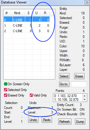
Three Continuous Lines
In the Database Viewer above is a drawing with three entities, all continuous lines.
The continuous lines were placed by three separate operations, such as the continuous line or rectangle tools.
Each entity has an undo level, consecutively 1, 2, and 3, corresponding to each of the three
operations used to draw the entities.
All of the entities have a redo level of 0, meaning they cannot be redone.
The drawing has a current undo level of 3, corresponding to the last drawing operation.
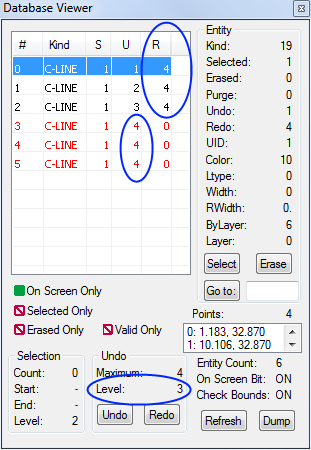
After a Modify Command
In the Database Viewer above is the same drawing after modifying all three entities, for example,
by selecting all three at once and moving them.
The three original continuous lines remain in the drawing but have been erased.
Because they were erased, they can be redone, which is to say they can be unerased.
The redo level is 4, corresponding to the operation used to modify and erase the entities.
Three new modified continuous lines have been added to the drawing.
Each new entity has an undo level of 4, likewise corresponding to the operation used to draw the entities.
The drawing has a current undo level of 4, corresponding to the last drawing operation.
Undo/Redo Applied
The current undo level of the drawing is the level which will be applied to the next undo or redo operation
on the drawing, including the Undo and Redo native commands and the API functions
VCUndo and VCRedo.
The Undo command will decrease the current undo level of the drawing
whereas Redo will increase it, thereby allowing Undo and Redo to step through
the entire sequence of available undo and redo operations.
Undo will erase all entities with an undo level equal to the drawing undo level.
Undo will unerase all entities with a redo level equal to the drawing undo level.
After being undone, the drawing undo level will be decremented by one.
Redo will unerase all entities with a redo level one greater than the drawing undo level.
Redo will erase all entities with an undo level one greater than the drawing undo level.
After being redone, the drawing undo level will be incremented by one.
Undo
In the Database Viewer above is the same drawing after performing Undo.
Recall the Undo command was used when the drawing undo level was 4
(see the previous example above).
Therefore, the three continuous lines which were previously unerased with undo levels 4
have been erased - the undo level equal to the drawing undo level.
And, the three continuous lines which were previously erased with redo levels 4
have been unerased - the redo level equal to the drawing undo level.
After being undone, the drawing undo level has been decremented to 3.
Redo
In the Database Viewer above is the same drawing after performing Redo.
Recall the redo command was used when the drawing undo level was 3
(see the previous example to the left).
Therefore, the three continuous lines which were previously unerased with redo levels 4
have been erased - the redo level one greater than the drawing undo level.
And, the three continuous lines which were previously erased with undo levels 4
have been unerased - the undo level one greater than the drawing undo level.
After being redone, the drawing undo level has been incremented to 4.
Note the difference between the undo and redo levels affected by Undo and Redo:
Undo affects entities with undo and redo levels equal to the current undo level of the drawing.
Redo affects entities with undo and redo levels one greater than the current undo level of the drawing.
Setting the Undo/Redo Levels
Native Visual CADD™ tools which support undo/redo normally support one undo/redo level
(there are exceptions) and internally operate as follows:
The tool starts by incrementing the drawing undo level.
Entities added by the tool are given an undo level equal to the current drawing undo level (after incrementing) and a redo level of 0.
Entities erased by the tool are given a redo level equal to the current drawing undo level (after incrementing).
If the tool is aborted before it completes, the drawing undo level is decremented back to its original value and any changed entities are restored
to their original conditions.
Custom add-on tools created using the API and designed to support undo/redo must perform the same steps as the native Visual CADD™ tools.
The API provides several functions for managing undo and redo.
Please refer to the Managing Undo and Redo topic for details.